

With no clutches and a single gear reduction, GRT servos are the epitome of simplicity and reliability. There are practically no mechanisms to fail. Safety features are abundant, including an shear-able output arm that remains captive to prevent jamming, and a safety-wired case. Limited authority means you can take over, even if you forget to disconnect the autopilot. Motor temperature sensing prevents motor damage without sacrificing torque. Pitch servos include an optical force sensing mechanism, that will never wear out, to keep the pilot aware of trim required. Even the drive electronics protects themselves from extreme conditions.
$0.00
Autopilot/Flight Director
Every GRT Avionics display unit, from the first WS, through our Horizon 10.1 flagship, as well as the Mini-EFIS, is capable of performing as an autopilot control head. Just connect one or two servos and we will fly you from just after takeoff, to just before touchdown. We will couple you to your approach and fly you to your selected altitude…and much more!*
No servos? No problem! The flight director makes you the autopilot, combining attitude and navigation targets into a single cue that even a non-pilot can follow.
*Vertical autopilot functions are optional with some display units.
Smooth and Accurate – Exceptional in Turbulence
All autopilots are not created equal. More than many other aspects of an EFIS, the autopilot depends on the mathematics and logic that drive the servos to deliver the performance you expect. Our engineering background includes autopilot experience with commercial and military aircraft. The result is a smooth and accurate autopilot that with ride quality in turbulence superior to hand flying. Our claims are exceptional, but they are met by our autopilot performance.
But the autopilot isn’t just about flying the airplane with servos. It is also about working with the pilot.
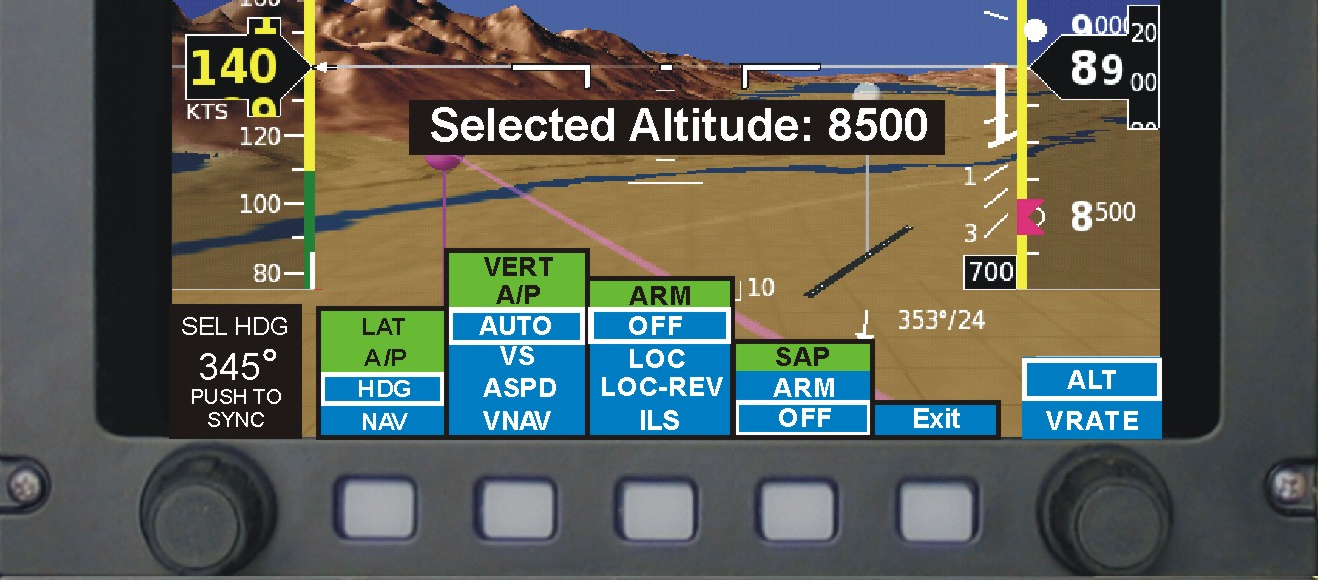
Simple to Engage

Simple to Command
Yes, We Couple to That…
Lateral and vertical coupling is only limited by the navigation sources connected to the EFIS, such as GPS, VOR, ILS, LOC, and even lateral and/or vertical steering commands from an external GPS. Coupling to the synthetic approach is also provided, and may be used with all approaches, visual or instrument.
Pitch Trim Sensing


Providing Awareness
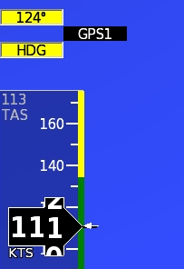
Here the autopilot was coupled to GPS1, but it is unable to provide navigation guidance because it lacked a flight plan or lost GPS position lock. The EFIS autopilot reverted to heading hold until GPS1 is restored. The heading hold mode, and its target is clearly displayed in yellow, and GPS1 shown pending. On the right, the vertical mode is currently in IAS climb mode at 125 knots, and will level off at 8,000’. No vertical modes are pending.
The Same Approach- IFR or VFR
Traditional coupling to lateral and vertical navigation sources for IFR approaches is included and augmented with the automatic capture feature. Similarly, VFR approaches can be flown coupled to any runway in the database also by coupling to the synthetic approach. We took it one step further. Recognizing the benefit of making every approach the same, so we allow you to fly the approach the same, IFR or VFR. IFR requires only that you tune the ILS. The EFIS will take it from there. Highway-in-the-sky guidance will supplement the raw data ILS display and autopilot coupling will function the same as a synthetic approach.
A Backup to the Nav Radio
Our synthetic approach normally defaults to extended runway centerline, and your default setting for the glideslope angle. This is great for VFR, but is provides no assurance of obstacle clearance. However, when the EFIS sees (via its database) that the runway you have selected includes an Loc or ILS approach, it will construct its synthetic approach to emulate the actual approach. This provides greater assurance of obstacle clearance and is a last-chance backup to an ILS receiver.
Safety
A well-designed autopilot is driven more by safety than its primary job of flying the airplane. Safety must consider much more than mechanical failures, but also its role when working with the pilot. Some of our safety features include:
- Pitch servo torque sensing with out-of-trim annunciation and alerting
- Clear and unambiguous annunciation of the current and pending modes
- Continuous self-test of servo electronics and communication
- Under-speed/over-speed/g-limiting
- Unusual attitude recovery
- Driven by high-integrity attitude data
- Annunciation of autopilot disconnect
- Safe mechanical design and its mounting
- Attention to these issues reflects our engineering experience with commercial, military and experimental aircraft. Like our AHRS, our autopilot is designed to a higher standard.
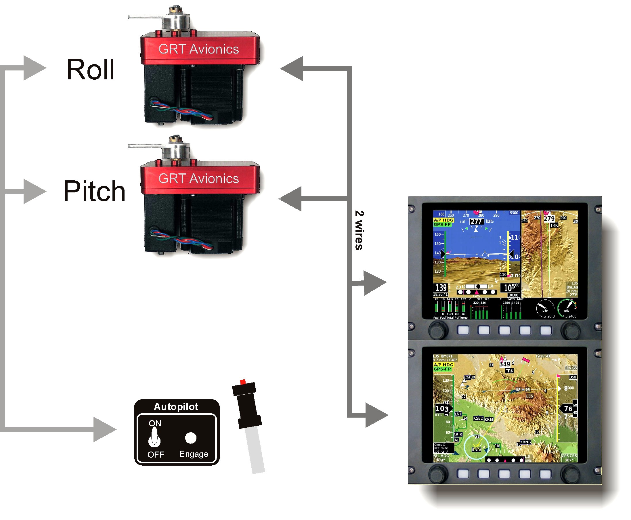
System Architecture
GRT servos can be wired to all display units. AHRS attitude/air data is used to drive the autopilot, and is displayed to the pilot. Want redundancy? Upgrade to a dual AHRS, and you get redundant, cross-checked, attitude/air data not just to your displays, but also for your autopilot.
Easy to Maintain!
No regular maintenance is required, and like all GRT equipment, servo software can be updated without removing it from the airplane.
Mounting Kits
Factory approved mounting kits are available for all popular kitplanes. Order your servo with your EFIS, or add it later for the same low price at anytime.