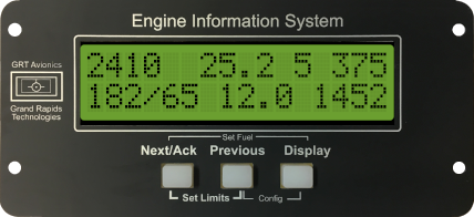
Basic Monitoring for two-stroke engines. EGT/CHT inputs for 2 cylinders plus 1 Aux input
Includes wiring harness.
$503.00
EIS Engine Monitors
From two cycle to turbine and everything in between, the award-winning Engine Information System, or EIS, has been a leader in reliable aircraft engine monitoring since 1991, with over 24,000 instruments flying. Its simple LCD screen can give you vital engine information as a stand-alone unit. Active warnings are sent instantly to the pilot in the form of a warning light or blinking message on the GRT EFIS display. Options include fuel flow, integrated altimeter and airspeed indicator, and a multitude of sensors for engines, electrical systems, and fuel systems.
Large, Sunlight-Readable, Backlit Display
Easy to read! No more playing games to figure out what is being displayed. No flickering displays. Simple, continuous readouts of all cylinders at one time with user-customizable pages and press-to-see labels.
Blind Mounting
You can blind-mount EIS anywhere behind the firewall and view all of its information on a GRT EFIS. With a single-wire serial connection, the EIS can feed full engine and systems data to a GRT EFIS display unit to create full-color, customizable graphic engine information displays, as well as the ability to save & upload engine data to analysis services such as SavvyAnalysis.com.
Flexible Leaning Pages*
Most instruments allow you to lean according to the technique the instrument designer had in mind; a necessary compromise due to the limited information provided on their small displays. The EIS uses a 32-character display and 5 different pages of EGT data (models 4000, 600 and 9000 only). This makes leaning your engine easy, no matter what your leaning technique. Our digital leaning page has proven to be a very popular function. It shows when each cylinder has reached peak and how far past peak it is with one degree resolution.
Cruise Monitor*
Digital and graphical display of the EGT trends. This function reveals which cylinder is causing your engine to run rough, or reassures you that all is well when setting out over hostile terrain. The costs savings in maintenance provided by this function easily justifies the cost of the entire instrument. More useful and important than the leaning function.
EIS Leaning Function*
The EIS tells you which cylinders are past peak, which cylinder peaked first, and how far each cylinder is away from peak. The leaning status of all cylinders is displayed simultaneously, making it simple to see how well balanced the mixture is to the engine.
Value
Save fuel and increase range by leaning correctly. Reduce maintenance costs by detecting problems early and diagnosing problems to the affected cylinder thanks the extensive monitoring and alerting provided by the EIS.
EMI Tolerance
The installation of the instrument and its wiring is completely non-critical. Special routing of wires or other considerations are not necessary, as the instrument is able to tolerate any level of electromagnetic interference (EMI) present in an airplane. Emissions from the instrument are practically non-existent, so that it will not affect radios or other equipment.
* Models 4000, 6000 and 9000 only.


